
Engineering guide · Electronics manufacturing
Electronics Industry Metal Fabrication: A Complete Guide
From a compact PCB enclosure to a large industrial control cabinet, fabricated metal parts help protect, cool, ground, and support electronic assemblies. We explain the materials, processes, finishes, quality considerations, and supplier questions that matter when taking an electronics part from drawing to production.
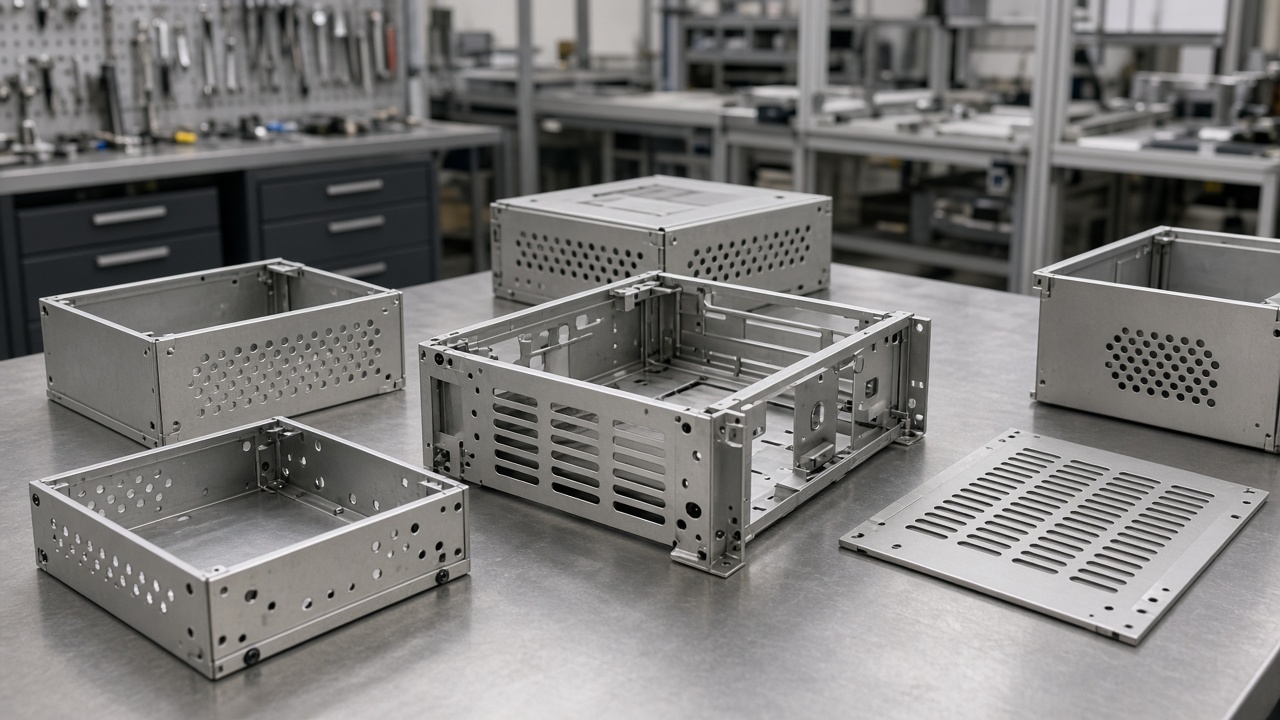
Introduction: Why Metal Fabrication Matters in Electronics
A phone, an industrial drive, a laboratory instrument, and an automation controller may have very different functions, but each relies on physical parts that keep its electronics protected and operating reliably. Metal enclosures, chassis, brackets, heat spreaders, shields, and contacts provide the structure around delicate boards and electrical components.
Electronics industry metal fabrication is the engineering and production of these metal components for electronic products and equipment. It brings together material selection, cutting, forming, joining, finishing, and inspection. In this guide, we walk through those choices, explain common applications and emerging technologies, and outline how to evaluate a fabrication partner for prototype and production work.
The enclosure is not just a cover. Its geometry and material can affect fit, heat flow, grounding, shielding, serviceability, and the finished product’s appearance.
What Is Electronics Metal Fabrication?
Electronic fabrication is the process of manufacturing electronic products or assemblies, including the boards, components, and supporting parts that make them function. Metal fabrication is one part of that wider process: it produces the metal housings, shields, chassis, brackets, and other components that contain and support electronics.
Compared with many general-purpose sheet metal jobs, electronics parts can demand more attention to fit with PCBs and connectors, controlled openings and ventilation, grounding paths, thermal behavior, surface cleanliness, and repeatability. A small positional error at a connector cutout, for example, can complicate assembly even when the overall enclosure dimensions look correct. Requirements should therefore be set on the drawing and checked against the intended assembly.
Where fabrication fits
Metal fabricators are part of the manufacturing sector and the supply chains serving industries such as electronics, automotive, aerospace, medical equipment, energy, and industrial machinery. We work with OEM engineering, procurement, quality, and operations teams to turn part drawings into buildable components and assemblies.
Core Applications in the Electronics Industry
The same fabrication methods can produce very different electronic parts. The application determines what the part must protect, support, conduct, dissipate, or shield—and that function should guide its material and design.
Enclosures and Chassis for Boards and Drives
Sheet metal enclosures protect printed circuit boards, power supplies, drives, and control assemblies from handling damage and the surrounding environment. The design may include formed panels, access covers, mounting points, connector cutouts, cable entries, and ventilation patterns. Bend dimensions and tolerances influence how those features align when the enclosure is assembled; connector openings should be checked against the actual mating hardware and PCB position, not only the outside dimensions.
Heat Sinks and Thermal Management Solutions
Metal conducts heat away from components and helps transfer it to surrounding air or another thermal interface. This matters in power electronics, drives, and LED equipment, where heat can affect component life and operating stability. Aluminum combines relatively low weight with useful thermal conductivity and is common in housings and heat-spreading parts. Copper conducts heat exceptionally well, but its higher weight and material cost can make it more appropriate for specific high-conductivity features than for a large general enclosure. Final thermal performance also depends on contact surfaces, airflow, geometry, and the overall system design.
EMI/RFI Shielding and Electrical Protection
Electromagnetic interference (EMI) and radio-frequency interference (RFI) are unwanted electromagnetic disturbances that can affect device operation. A conductive enclosure or shield can help contain or block interference when it is designed as part of a complete electrical system. Grounding points, panel seams, openings, fastener locations, and conductive gaskets all influence continuity across the enclosure. A coating that insulates the mating surfaces may interrupt a grounding path, so the drawing should identify where bare or conductive contact is required.
Design note
Treat shielding as a system requirement. Specify bonding and grounding intent, seam treatment, and any conductive gasket requirements early, then validate the assembled product against its applicable performance criteria.
Mounting Brackets and Structural Components
Brackets, racks, frames, panels, and internal supports hold boards and equipment in position and help maintain alignment during assembly, transport, and service. Formed parts can consolidate several functions into one component, while punched holes, louvers, and hardware features can reduce separate operations. For an assembly, define the datums and attachment points that control fit, and consider tool access for installation and maintenance.
Stamped Electronic Components
Stamped contacts, terminals, and connector elements are produced by shaping sheet or strip material with tooling. Once the process and tool are established, stamping can provide repeatable parts at volume and support detailed features. Material temper, thickness, burr direction, edge condition, and plating requirements are important inputs for electrical contacts. Progressive-die tooling is a specialized investment, so it is usually considered when volumes and part geometry justify the tooling approach.
Materials Used in Electronics Metal Fabrication
Electronics use a range of metals, selected according to whether a part needs to conduct electricity or heat, provide structure, resist corrosion, or meet a weight and cost target. Common choices include aluminum, stainless steel, copper, brass, carbon steel, and zinc alloys. The table below is a starting point; a part’s actual grade and temper should be specified for its application.
| Metal | Common strengths | Typical electronics uses |
|---|---|---|
| Aluminum | Low weight, useful thermal conductivity, and good machinability | Enclosures, panels, heat spreaders, and machined features |
| Stainless steel | Strength and corrosion resistance | Equipment exposed to demanding environments, including medical and laboratory equipment |
| Copper and brass | High electrical and thermal conductivity; brass can also suit formed or machined contacts | Busbars, contacts, terminals, and selected shielding applications |
| Cold-rolled and galvanized steel | Cost-effective structural material; galvanized grades provide a protective zinc coating | Cabinets, chassis, covers, and support components where conductivity is not the primary requirement |
| Zinc and specialty alloys | Can support detailed shapes and compact precision features, depending on alloy and process | Die-cast housings and small precision components |
Aluminum
Aluminum is useful when designers want to reduce mass without giving up practical strength or thermal performance. It can be cut, formed, and machined, and anodizing is available when a protective or decorative surface is required. We work with aluminum grades including 5052, 6061, and 5754; the best choice depends on the part’s forming, strength, and finishing needs.
Stainless Steel
Stainless steel offers corrosion resistance and strength for equipment that may face moisture, cleaning, or other harsh service conditions. It is used in industrial, medical, and laboratory equipment when those characteristics suit the design. Grade, finish, weld details, and cleaning expectations should be considered together. Available sheet grades at Rapidsheetfab include SUS304, SUS316, and SUS430.
Copper and Brass
Copper is selected where electrical or thermal conductivity is a priority, including busbars and some shielding or heat-transfer parts. Brass is used for conductive contacts, terminals, and components where its material properties and formability fit the application. Specify the required alloy clearly: Rapidsheetfab works with copper C1100/T2 and brass H62.
Steel (Cold-Rolled and Galvanized)
Cold-rolled steel is often a practical, economical choice for enclosures and structural parts when low weight or high electrical conductivity is not the main design driver. Galvanized grades add a zinc coating for corrosion protection. For either type, account for the coating when specifying cut edges, welds, cosmetic expectations, and any later paint or powder-coat finish.
Zinc and Specialty Alloys
Zinc alloys and other specialty metals can be appropriate for die-cast housings or small precision parts where the shape, volume, and required properties support that process. These materials are not interchangeable with sheet metal grades; confirm the manufacturing route, applicable alloy specification, and finishing requirements during design review.
Material Selection Criteria
We recommend comparing conductivity, weight, cost, corrosion resistance, machinability, formability, and finish compatibility against the part’s actual function. Also consider the assembly: a conductive enclosure with an insulating coating may need deliberate grounding points, while a light housing may need additional formed features to provide stiffness. Call out the material grade and thickness on the drawing rather than relying on a generic description such as “aluminum sheet.”
Fabrication Processes That Deliver Precision
Process choice depends on the part geometry, material, thickness, quantity, tolerance, finish, and delivery plan. A component that is economical to laser-cut and bend for a prototype may need different tooling for a stable high-volume run.
Cutting: Laser, Plasma, Waterjet, and Punching
Laser cutting is a flexible option for sheet parts and detailed profiles. Fiber lasers are especially useful for fine features and small holes when the material and thickness support the design. Plasma cutting is generally associated with thicker conductive materials and can have a different edge condition than laser cutting. Waterjet cutting avoids a heat-affected edge but may trade cutting speed for that capability. CNC punching is efficient for repeated holes, louvers, and formed features, particularly when the layout suits the available tooling.
| Process | Considerations | Good fit when |
|---|---|---|
| Fiber laser | Fine profiles and detail; thickness range and edge quality depend on material and machine capability | The part has varied outlines, small holes, or changing prototype geometry |
| Plasma | Useful on suitable conductive materials; edge quality and heat input differ from laser processes | Part thickness and application allow its cut quality |
| Waterjet | Avoids thermal cutting effects; cycle time and edge requirements need review | The material or application benefits from a non-thermal cutting method |
| CNC punching | Tooling-dependent; efficient for repeated holes, louvers, and suitable formed features | The feature pattern repeats and matches available punch tooling |
At Rapidsheetfab, our five fiber laser cutters handle sheets up to 2000 × 4000 mm. Listed maximum laser cutting capacities are up to 20 mm for stainless steel, 25 mm for carbon steel, and 16 mm for aluminum; practical part capability depends on the drawing and application. Our typical sheet metal range is 0.5–12 mm.
Forming: Press Brakes and Roll Forming
Press brakes form sheet into flanges, returns, channels, and other bends. A design must account for bend allowance, inside radius, tooling access, and springback—the material’s tendency to recover slightly after forming. Feature placement near bends can also affect whether a part forms cleanly. Roll forming is suited to producing long, consistent profiles through a series of forming stations. For either approach, share the material grade and thickness and identify the dimensions that control assembly fit.
Practical DFM tip
If a bend controls a connector, PCB, or cover interface, mark the relevant datum and tolerance explicitly. Agree on bend direction and finished dimensions before releasing the part for repeat production.
Stamping and Progressive Die Work
Stamping uses matched tooling to cut and form parts in a repeatable production cycle. Progressive dies perform a sequence of operations as material advances through the die. This can be advantageous for high-volume contacts, terminals, and other repeated components, but tooling design and investment should be balanced against expected volume, revision risk, and required feature consistency. For early product development or changing geometry, a flexible cutting-and-forming route may be more practical.
Joining: Welding, Riveting, PEM Hardware, and Adhesive Bonding
Welding can create rigid assemblies, while riveting and inserted hardware can provide mechanical joints without a continuous weld. PEM hardware and tapped holes support removable fasteners and service access. Adhesive bonding may suit specific material combinations or surfaces when its performance is qualified for the application. For visible or conductive assemblies, specify weld appearance, distortion limits, surface treatment, and any masking or bare-metal contact areas. A joint should be chosen for function, assembly sequence, maintainability, and finish—not just ease of fabrication.
Rapidsheetfab offers TIG, MIG/MAG, laser, and spot welding, as well as PEM hardware insertion and riveting. We also support M2–M12 tapping, subject to drawing and part review.
Machining and Secondary Operations
CNC milling, drilling, tapping, and insert installation can finish features that are difficult to produce during sheet cutting and forming. Secondary operations may also include deburring, grinding, brushing, basic polishing, and assembly. Identify threaded-hole sizes, insert types, critical edge conditions, and cosmetic surfaces on the drawing. Bundling compatible operations with one supplier can reduce handoffs, but drawings and inspection requirements still need to define how the completed part is accepted.
Finishes and Coatings for Electrical Assemblies
A finish can improve corrosion resistance, wear performance, appearance, solderability, or electrical behavior. It can also change dimensions, mask a conductive surface, or affect assembly fit. Define the finish, color or appearance, coating thickness where applicable, and any masking or grounding requirements before fabrication begins.
Powder Coating and Painting
Powder coating and painting can provide durable surface protection and a broad choice of colors for cabinets, panels, and visible equipment. These finishes are typically electrically insulating, so they should not cover grounding or bonding interfaces unless the design accounts for that layer. Specify which faces are cosmetic, where coating must be masked, and what appearance standard applies to the finished product.
Anodizing
Anodizing forms a controlled oxide layer on aluminum. Standard anodizing is used for protection and appearance, while hard-coat anodizing is selected when a harder, more wear-resistant surface is needed. Anodized surfaces are generally non-conductive across the treated area, so electrical contact zones may need to be masked or designed separately. Confirm the anodize type and cosmetic expectations with the finishing provider.
Plating (Nickel, Tin, Zinc, Chromate-Free)
Nickel, tin, zinc, and other plating options can be used for corrosion control, electrical contact performance, solderability, or a defined surface appearance. The right choice depends on the base metal, contact requirements, operating environment, and downstream process. When regulatory restrictions apply, request documentation for the specified finish and discuss RoHS or REACH requirements. Chromate-free alternatives may be required by the project specification.
Conductive Coatings for Shielding
Conductive paints and platings can help maintain electrical continuity on a surface that would otherwise be insulating or poorly conductive. Their usefulness depends on coating coverage, contact pressure, seam design, grounding, and long-term interface performance. Do not assume that a decorative metallic-looking finish is electrically conductive. Specify the intended bonding surfaces and verify the completed enclosure in its assembled condition.
Rapidsheetfab coordinates powder coating, anodizing, plating, passivation, sandblasting, electropolishing, screen printing, and laser marking through qualified finishing partners. These finishing processes are not represented as wholly in-house operations; availability and requirements are confirmed against each project.
Design Trends Shaping Electronics Metal Fabrication
Miniaturization of Electronic Products
As products become smaller, parts may use thinner gauges, tighter feature spacing, and more compact connector or mounting layouts. That puts greater emphasis on process capability, material behavior, burr control, and tolerance stack-up. Designers can help by identifying critical-to-fit dimensions and avoiding unnecessarily tight tolerances on non-functional features.
Thermal Management in Higher-Power Devices
Higher-power electronics place more attention on heat spreading and airflow. Integrated heat spreaders, formed surfaces, and fin designs can help move heat through or away from an assembly, but fabrication features must work with the system’s thermal interfaces and airflow path. Validate the mechanical design with thermal analysis or testing appropriate to the product; a metal part alone cannot guarantee cooling performance.
Customization and Rapid Prototyping
Custom sheet metal prototypes let engineering teams check fit, access, connector alignment, and enclosure appearance before locking a design. Short runs and fast drawing iterations can support new product introduction without committing prematurely to production tooling. We support a minimum order quantity of one piece for prototypes, with prototype timing depending on the process and drawing requirements.
Aesthetics and Surface Quality
Visible enclosures in consumer, medical, and laboratory products may need consistent grain direction, clean edges, controlled weld appearance, and a repeatable color or texture. These expectations should be made measurable where possible. Identify show surfaces, acceptable handling marks, protective packaging needs, and whether the finish must match a reference sample or specified coating system.
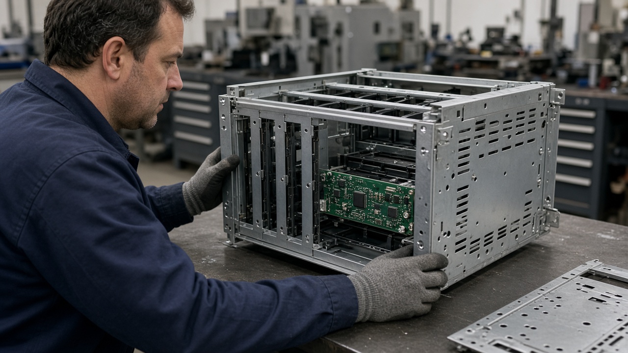
Latest Technologies in Metal Fabrication
The latest advances combine more capable machines with connected engineering and production workflows. These technologies can improve consistency and shorten iteration cycles, but their value depends on the part, volume, and supplier’s actual process capability.
-
1
Fiber laser cutting and automated handling
Fiber lasers support efficient, detailed cutting on suitable materials. Automated sheet or tube handling can reduce manual material movement and help keep production flow consistent.
-
2
Robotic welding and press brake automation
Robotic welding can support repeatable weld paths in appropriate production settings. Press brake automation and angle measurement can help manage forming consistency and reduce setup variation.
-
3
CAD/CAM, simulation, and nesting
Digital programming links geometry to manufacturing operations. Simulation can help anticipate springback, while nesting software arranges parts to use sheet material efficiently.
-
4
Digital quoting and DFM feedback
Digital RFQ workflows can speed drawing review and surface manufacturability questions earlier, such as bend access, feature proximity, and tolerance clarity.
-
5
Hybrid methods for development
Additive manufacturing can complement sheet metal work for prototypes, fixtures, or selected low-volume components. A hybrid approach lets teams use the process that best fits each feature rather than forcing every part into one method.
These are wider industry trends, not a statement that every supplier has every technology. When comparing vendors, ask which capabilities are available for your specific part and which are provided through qualified partners.
Quality Standards and Certifications
Certifications, material declarations, inspection records, and traceability help buyers determine whether a supplier can meet the project’s quality system and regulatory requirements. Requirements vary by end market and customer. Ask for the current scope and relevant evidence rather than assuming a general certification covers every process or product.
ISO 9001 and AS9100
ISO 9001 establishes a quality management system framework for consistent processes and continual improvement. AS9100 adds aerospace-specific requirements and controls. Rapidsheetfab is ISO 9001:2015 certified; we do not claim AS9100 certification. If an aerospace project requires AS9100, confirm certification scope with the supplier before placing an order.
IATF 16949 and ISO 13485
IATF 16949 is associated with automotive quality management, while ISO 13485 addresses quality systems for medical devices. A project may also impose customer-specific controls. These standards should not be inferred from a supplier’s general manufacturing experience: verify the required certification, its scope, and the supplier’s role in the regulated supply chain.
RoHS, REACH, and UL Compliance
RoHS and REACH requirements can affect material and finish choices, declarations, and documentation. UL requirements may apply to the finished product or particular components, depending on its design and market. Clearly state the applicable standard or customer requirement in the RFQ, and confirm exactly what documentation or listed component is needed. Rapidsheetfab can provide available RoHS/REACH documents and material certificates; compliance should be checked against the project’s precise specification.
Inspection and Measurement
A good inspection plan checks the features that determine fit, function, and acceptance—not just overall size. First article inspection (FAI) records the initial build against the drawing. Coordinate measuring machines (CMMs), vision systems, height gauges, and standard inspection tools can support dimensional verification. Statistical process control (SPC) may be used where a customer and process plan call for ongoing measurement of key characteristics.
- Define critical features: Mark fit, hole-position, bend, and cosmetic requirements clearly on the drawing.
- Agree on records: State whether you need an FAI, dimensional report, material certificate, or coating report.
- Plan traceability: Identify any required lot identification, revision control, or material tracking before production.
Rapidsheetfab’s quality flow includes IQC, FAI, IPQC, FQC, and OQC. Inspection resources include a CMM, 2.5D vision systems, height gauges, and standard inspection tools. Available project documentation includes first article inspection, dimensional reports, material certificates, RoHS/REACH documents, and coating reports.
From Prototype to Production
Prototype work should do more than prove that a part can be made. It should reveal fit, assembly, finish, and inspection issues early enough to improve the design before volume increases. A practical build path typically looks like this:
-
1
DFM review
Review the 2D drawing and 3D model for material, tolerances, bend feasibility, joining, finish, and assembly constraints.
-
2
Prototype build
Make one or a few parts to check critical interfaces, enclosure access, grounding details, and appearance.
-
3
Pilot run
Confirm repeatability, assembly sequence, inspection expectations, packaging, and any process adjustments at a small production quantity.
-
4
Production release
Freeze the approved revision, purchase quantities, inspection plan, and documentation requirements for ongoing orders.
Tooling investment and lead time change with process and volume. A laser-cut prototype generally avoids dedicated stamping tooling, while progressive-die production requires more upfront planning and tool investment. At Rapidsheetfab, typical prototype lead time is 3–12 working days depending on the process, small batches typically require 10–15 days, and regular production typically requires 15–25 days. These are planning ranges, not guaranteed dates; confirm the schedule against the actual drawing, finish, quantity, and documentation.
Keep revisions controlled
Send the current drawing revision and model together, and identify which document governs if they differ. Keep approved samples, inspection reports, material certificates, and change records linked to the relevant part revision and production lot when traceability is required.
How to Choose an Electronics Metal Fabrication Partner
For an OEM, a good partner should do more than quote a flat pattern. Look for clear engineering feedback, realistic process limits, consistent quality communication, and a path from the first prototype through repeat orders. Ask for evidence that maps to your part and requirements.
Capabilities and Equipment Checklist
Compare the supplier’s equipment and processes with the actual part envelope, material, thickness, tolerances, finish, and assembly needs. For an electronics enclosure, the right combination may include cutting, bending, punching, hardware insertion, welding, and finishing coordination.
- Cutting and size range: Ask about sheet size, materials, thickness limits, and achievable feature details.
- Forming capacity: Confirm press-brake capacity, maximum part length, bend sequence, and how tolerances are agreed.
- Assembly processes: Check availability of welding, tapping, PEM hardware, riveting, and related operations.
- Quality and finish: Ask what inspection equipment and documentation are available, and which finishes are handled through partners.
Rapidsheetfab has five fiber laser cutters for sheets up to 2000 × 4000 mm and seven CNC press brakes with capacity up to 230T / 3000 mm. Additional capabilities include CNC punching, TIG, MIG/MAG, laser and spot welding, PEM hardware insertion, riveting, M2–M12 tapping, deburring, grinding, brushing, basic polishing, and assembly. Typical drawing-dependent tolerances are laser cutting ±0.10 mm, bending ±0.20–0.30 mm, and holes ±0.10–0.20 mm; confirm applicable tolerances for the specific design and process.
Experience in Electronics Applications
Ask how the supplier handles board and connector clearances, grounding areas, seam continuity, ventilation, thermal features, and cosmetic surfaces. Experience with industrial controls, drives, instruments, or similar equipment can help a fabricator recognize design risks early. Request relevant examples or references where available, while respecting customer confidentiality.
Engineering Support
Early design-for-manufacturability feedback can reduce avoidable rework and help clarify how a part will be built and inspected. A useful review identifies specific drawing questions, suggests practical process alternatives, and explains any tolerance or finish concerns. Provide a PDF for clear review plus a DXF or 3D model when the project requires geometry data; STEP and native CAD formats can help resolve complex assemblies.
Scalability and Supply Chain
A prototype supplier should also be able to explain how the approved design transitions into low-volume and repeat production. Evaluate capacity, lead-time communication, revision control, documentation, packaging, and how externally provided finishing is coordinated. A consolidated supplier can reduce handoffs when it can manage the required fabrication and assembly operations while keeping process ownership clear.
Questions to Ask Before You Request a Quote
- Can you review our drawings and flag manufacturability or assembly risks before production?
- Which tolerances can you commit to for the specified material, thickness, and process?
- Can you support the prototype, pilot quantity, and expected production volumes?
- What inspection reports, material certificates, or finish documents can you provide?
- Which operations are in-house, and which are performed by qualified finishing or process partners?
Frequently Asked Questions
What industry is a metal fabricator in?
Metal fabrication is part of the manufacturing sector. Fabricators supply components and assemblies to electronics, automotive, aerospace, medical, energy, and industrial equipment supply chains.
What is electronic fabrication?
Electronic fabrication is the manufacture of electronic products and assemblies. Metal fabrication supports that work by producing enclosures, chassis, shields, heat-transfer parts, brackets, and other metal components. See What Is Electronics Metal Fabrication? for more detail.
What are the latest technologies in metal fabrication?
Current developments include fiber laser cutting, automated material handling, robotic welding, press brake automation with angle measurement, CAD/CAM simulation, optimized nesting, digital quoting, DFM tools, and additive manufacturing for selected prototypes or fixtures. Read Latest Technologies in Metal Fabrication.
What metals are electronics made of?
Common metals include aluminum for lightweight housings and thermal parts; copper and brass for conductive components; stainless steel for strength and corrosion resistance; cold-rolled or galvanized steel for enclosures and supports; and zinc alloys for selected die-cast housings. The appropriate metal depends on the component’s electrical, thermal, mechanical, environmental, and cost requirements.
Conclusion: Building Reliable Electronics with the Right Fabrication Approach
Reliable electronics metal fabrication starts with a clear understanding of what each part must do. Material and process choices affect conductivity, heat flow, weight, corrosion resistance, assembly fit, appearance, and cost. Enclosure seams, grounding interfaces, coatings, and tolerances all deserve attention when shielding and electrical performance matter.
We recommend defining functional requirements, critical dimensions, finish expectations, applicable compliance needs, and inspection records early. Involving a fabrication engineer during design review can expose process or assembly concerns before they become production problems—and help carry a design from a one-piece prototype into repeat manufacturing.
Start a project discussion
Get a Quote for Your Electronics Metal Fabrication Project
Share your drawings, material and finish requirements, quantities, target delivery, and any critical inspection or traceability needs. We can review the design for manufacturability and discuss a prototype or NPI build to reduce risk before production.
For a useful RFQ review, include the current drawing revision and available PDF, DXF, STEP, or similar files, along with prototype and forecast quantities.