
Custom Sheet Metal Fabrication
Equipment Covers Built to Drawing
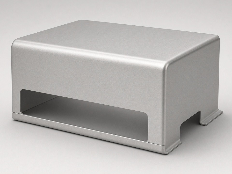
Rapidsheetfab builds equipment covers to drawing for industrial OEMs. These parts protect machinery, electronics, and automation systems while meeting dimensional, cosmetic, and structural requirements.
Material Selection for Equipment Covers
Equipment covers commonly use 1.5–4 mm sheet to balance weight and rigidity. The right alloy depends on the environment, load, and appearance requirements of the finished assembly.
Stainless Steel
SUS304 and SUS316 handle wash-down or corrosive settings.
Carbon Steel
SPCC and Q235 carbon steel suit painted indoor applications.
Aluminum
Aluminum 5052 and 6061 reduce weight in mobile or transport equipment.
Copper & Brass
Used in specialized electrical enclosures where conductivity or appearance matters.
Process Flow: Cutting to Finishing
Laser Cutting and Hole Patterns
Fiber laser cutters process sheets up to 2000 × 4000 mm with ±0.10 mm typical tolerance. This supports large side panels, access doors, and ventilation cutouts in a single operation.
CNC punching adds formed louvers, embosses, and threaded standoffs without secondary drilling.
Press Brake Forming
Seven CNC press brakes handle bends up to 230 t and 3000 mm length. Typical equipment cover work includes 90° flanges, return edges for stiffness, and multi-bend chassis shapes.
Operators check first-article parts against customer drawings before running batches.
Welding and Hardware Assembly
TIG and MIG welding join frames and seams on stainless or steel covers. Spot welding secures overlapping panels where appearance allows.
PEM insertion, M2–M12 tapping, and rivet nuts are added after forming. Final assembly includes hinges, latches, and grounding studs when supplied in the drawing.
Surface Protection and Finishing
Parts leave the shop with deburring and edge breaking. Powder coating, anodizing, passivation, and electropolishing are completed through qualified local partners.
Screen printing and laser marking add labels or serial numbers. All finishing steps follow documented process controls.
Inspection and Documentation Flow
Quality checkpoints follow the part from incoming sheet to packed shipment, with records retained for traceability.
±0.10 mm
Hole tolerance via CMM and 2.5D vision
0.20–0.30 mm
Bend tolerance
-
1
IQC — Incoming Sheet
Incoming material is checked before release to production.
-
2
FAI — First Article Inspection
Critical dimensions are recorded on the first part.
-
3
IPQC — In-Process Monitoring
Bending and welding are monitored during runs.
-
4
FQC & OQC — Final Verification
Finished covers are verified before packing. Material certificates, RoHS statements, and coating thickness reports ship with each order.
Prototype to Production Path
One-piece prototypes move to 10–50 piece NPI builds, then into scheduled repeat orders. The same tooling and programs stay in place when volumes increase, avoiding requalification steps.
Stage 1
Prototype
One-piece builds for fit and function validation.
Lead time: 3–12 days
Stage 2
NPI Build
10–50 piece runs to bridge into volume production.
Same tooling and programs
Stage 3
Repeat Orders
Scheduled production with no requalification steps.
Lead time: 15–25 days
Request a Quote
Send STEP, SolidWorks, or PDF drawings with material, finish, and quantity details. Rapidsheetfab reviews geometry for manufacturability and returns pricing within one business day.
Email: [email protected]
Address: Sanjiang Industrial Zone, Hengli Town, Dongguan City, Guangdong Province, China
What to Include in Your RFQ
- — STEP, SolidWorks, or PDF drawing files
- — Material and finish specification
- — Quantity and target schedule
- — Any cosmetic or structural requirements