
Custom Electronic Chassis Fabrication
Electronic chassis protect internal components, provide mounting points, and manage thermal loads in automation, instrumentation, and power equipment. Most designs combine flat patterns with multiple bends, welded seams, and hardware inserts.
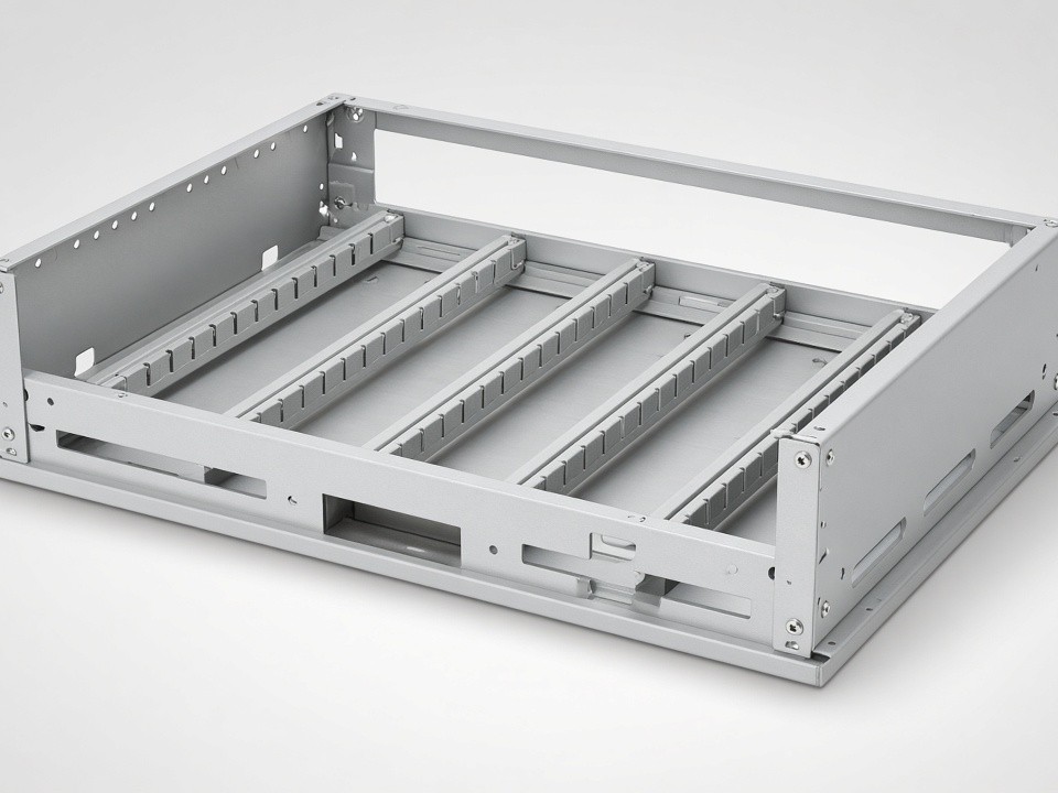
Sheet Metal Processes Used for Chassis
Each chassis build moves through a defined sequence of cutting, forming, joining, and surface preparation steps.
-
01 — Laser Cutting
Produces the base profiles and cutouts.
-
02 — CNC Punching
Adds louvers, vents, and precise hole patterns.
-
03 — Press Brake Forming
Forms the side walls and flanges.
-
04 — TIG / MIG Welding
Joins corners and internal brackets.
-
05 — PEM Insertion
Installs threaded standoffs and captive fasteners.
-
06 — Deburring & Surface Prep
Final preparation ahead of coating.
Capabilities Matched to Chassis Builds
Equipment and process coverage sized for enclosure work, from tall frames to fine hardware detail.
- Fiber Laser Cutting
- Five fiber lasers handle sheets up to 2000 × 4000 mm and cut stainless to 20 mm, carbon steel to 25 mm, aluminum to 16 mm.
- CNC Press Brakes
- Seven CNC press brakes reach 230 T and 3000 mm length for consistent flange angles on taller enclosures.
- Welding Stations
- TIG, MIG/MAG, laser, and spot methods for both visible seams and structural joints.
- Hardware Insertion
- Covers M2–M12 threads plus rivet and clinch nuts in one cell.
- Deburring & Finishing
- In-house deburring and brushing prepare surfaces before outside finishing partners apply powder coat, anodize, or plating.
Material and Tolerance Data
Common grades, working thickness ranges, and typical chassis applications.
| Material | Common Grades | Thickness Range | Typical Use in Chassis |
|---|---|---|---|
| Stainless steel | SUS304, SUS316 | 0.8–3 mm | Corrosion-resistant instrument housings |
| Carbon steel | SPCC, Q235, Q355 | 1–6 mm | Structural frames and base plates |
| Aluminum | 5052, 6061 | 1–4 mm | Lightweight panels and heat-dissipating covers |
| Copper / Brass | C1100, H62 | 0.5–2 mm | EMI shields and grounding plates |
Laser Cutting
±0.10 mm
Bending
±0.20–0.30 mm
Hole Position
±0.10–0.20 mm
Prototype to Repeat Production Path
A single-piece prototype order moves through the same equipment used for later batches. This continuity removes the need to requalify a new supplier when volumes increase.
-
First Samples
3–12 working days.
-
Small Runs
10–15 days.
-
Regular Production
Once drawings and processes are locked, production settles at 15–25 days.
Strong Fit
- —Chassis that require welded frames
- —Builds with multiple hardware types
- —Enclosures needing cosmetic finishing
- —Robotics controllers, lab analyzers, and power distribution units
Outside the Strongest Fit
- —Projects limited to simple laser-cut blanks
- —Work dominated by machined blocks
Request for Quotation
Send PDF, DXF, or STEP files along with material, finish, and quantity details. Include any critical dimensions, cosmetic zones, or packaging needs. The review returns a DFM note and lead-time confirmation within one business day.
Direct replies come from the same team that manages the order through inspection and shipment.
Email: [email protected]
Address: Sanjiang Industrial Zone, Hengli Town, Dongguan City, Guangdong Province, China