
Custom Sheet Metal Fabrication
Custom Automation Machine Frames
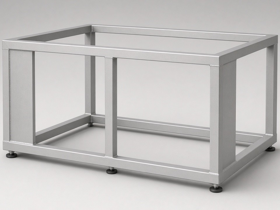
Industrial OEMs building automation equipment need frames that maintain alignment under repeated motion and load. Frames for robotic cells, conveyor modules, and assembly stations require consistent hole patterns, flat mounting surfaces, and welded joints that hold dimension after transport and installation.
Material and Thickness Options
Selection starts with the mechanical demands of the frame. Most automation frames use 2–6 mm material to balance stiffness against weight. Thicker sections apply where base plates carry motors or heavy tooling.
| Material | Common Grades | Thickness Range | Typical Frame Use |
|---|---|---|---|
| Carbon Steel | SPCC, Q235, Q355 | 1.5–8 mm | Structural uprights and bases |
| Stainless Steel | SUS304, SUS316 | 1.5–6 mm | Cleanroom or wash-down environments |
| Aluminum | 5052, 6061 | 2–6 mm | Lightweight gantries and enclosures |
| Galvanized Steel | SGCC, SECC | 1.2–4 mm | Indoor frames with moderate corrosion risk |
Fabrication Sequence for Frame Assemblies
This sequence keeps the part count low and reduces the chance of tolerance stack-up when multiple pieces assemble into one frame.
-
Step 1
Laser Cutting
Produces flat patterns with ±0.10 mm accuracy on critical hole locations.
-
Step 2
CNC Press Brake Forming
Forms the bends, holding ±0.20–0.30 mm on flange angles.
-
Step 3
Hardware Insertion
Places PEM nuts or studs before welding.
-
Step 4
Welding
TIG or MIG welds join the corners and cross members.
-
Step 5
Finishing
Deburring, grinding weld seams, and applying finish through qualified partners.
Volume Flexibility from Prototype to Repeat Orders
A single prototype frame ships in 5–10 working days once drawings are approved. The same process and tooling then support 10-piece or 50-piece runs without requoting setup charges.
Customers avoid switching suppliers when an initial test unit moves into field deployment or when annual volumes increase.
5–10
Working days for a single prototype frame after drawing approval
10–15
Days lead time for small batch runs
15–25
Days for regular production orders depending on finishing requirements
Documentation Delivered with Each Shipment
Every frame order includes dimensional reports from CMM or 2.5D vision inspection. These documents support incoming quality checks at the customer site and simplify audits for end users in automotive or medical equipment lines.
-
Dimensional Reports
From CMM or 2.5D vision inspection
-
First-Article Inspection
Records supplied on request
-
Material Certificates
Traceability for each order
-
RoHS Statements
Supporting audit and compliance needs
Projects That Match Our Process Range
Frames for cartesian robots, pick-and-place stations, and modular conveyor sections fit the 2000 × 4000 mm sheet capacity and 230-ton press brake limits. Welded base frames up to 3 m long with M8–M12 tapped inserts are produced regularly.
In Scope
- Cartesian robot frames
- Pick-and-place station frames
- Modular conveyor sections
- Welded base frames up to 3 m long with M8–M12 tapped inserts
- Laser-cut flat parts
Outside Typical Scope
- Projects requiring only laser-cut flat parts
- Heavy plate beyond 12 mm
Request a Quote for Your Frame Project
Send PDF, DXF, or STEP files with material, finish, and annual quantity. Include any critical datum surfaces or hole patterns that affect alignment. A DFM review and pricing response follows within two business days.
Email Drawings to [email protected]Or use the inquiry form to send your project details.