
Custom Sheet Metal Trays
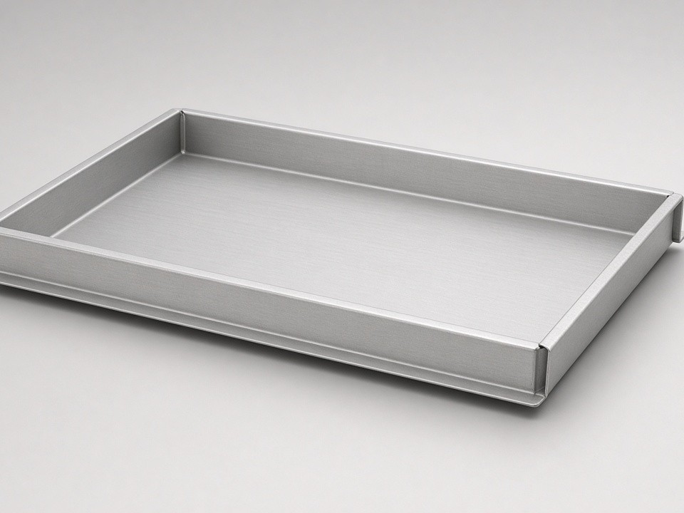
We fabricate sheet metal trays for enclosures, equipment bases, and material handling assemblies. Orders begin with one-off prototypes and move into scheduled production runs.
- Thickness Range
- 0.5–12 mm
- Cutting Tolerance
- ±0.10 mm
- Prototype Lead Time
- 3–12 days
Materials Selected for Tray Applications
Trays are produced from stainless steel, aluminum, and carbon steel grades chosen to match load and corrosion requirements. Copper and brass are used when conductivity or specific chemical resistance is needed.
Stainless Steel
SUS304 and SUS316 for corrosion resistance in demanding environments.
Aluminum
5052 aluminum for lightweight trays and equipment bases.
Carbon Steel
SPCC/CRS and Q235 steel for structural and general-purpose trays.
Copper & Brass
Specified when conductivity or chemical resistance is required.
Thickness starts at 0.5 mm and reaches 12 mm depending on load and corrosion requirements.
Laser Cutting and CNC Bending Operations
Five fiber lasers cut sheets up to 2000 × 4000 mm with ±0.10 mm tolerance on features. Seven CNC press brakes form parts up to 230 tons and 3000 mm long. These stations create tray sidewalls, flanges, and drainage patterns without secondary machining in most cases.
Fiber Lasers
- Sheet capacity up to 2000 × 4000 mm
- ±0.10 mm tolerance on features
- Clean cuts for sidewalls and drainage patterns
CNC Press Brakes
- Forming up to 230 tons
- Part length up to 3000 mm
- Sidewalls, flanges, and formed features
Welding, Assembly, and Feature Addition
Welding & Structural Assembly
TIG, MIG/MAG, laser, and spot welding join tray seams and mounting points. Welded assemblies receive grinding or brushing to meet cosmetic and functional surface conditions. Spot welding is applied where distortion must stay minimal on thin-gauge panels.
Hardware & Tapping
PEM inserts, rivets, and M2–M12 tapped holes are installed after forming.
Punching & Ventilation
CNC punching adds louvers, slots, and ventilation patterns directly into tray floors or walls. These operations occur in the same facility to keep lead times short.
Inspection and Documentation Flow
IQC, FAI, IPQC, FQC, and OQC checkpoints are applied to every batch. CMM and 2.5D vision systems verify critical dimensions. First-article reports, material certificates, and RoHS documentation are supplied on request.
Inspection Checkpoints
IQC & FAI
Incoming quality control and first-article inspection.
IPQC
In-process checks throughout fabrication.
FQC & OQC
Final and outgoing quality control before shipment.
Documentation
First-article reports, material certificates, and RoHS documentation on request.
Volume and Lead Time Expectations
One-piece minimums allow NPI builds to transition directly into ongoing supply without changing suppliers.
Prototype Trays
3–12
working days
Small Repeat Batches
10–15
days
Regular Production
15–25
days
Surface Treatment Coordination
Powder coating, anodizing, passivation, electropolishing, and screen printing are managed through qualified partners. These steps are quoted separately and scheduled after internal fabrication so the final part meets both dimensional and appearance specifications.
RFQ Submission Requirements
Send drawings in PDF, DXF, or STEP format along with material grade, quantity, finish, and any critical tolerances. Include target delivery dates and packaging instructions. Our engineering review returns DFM comments and pricing within one business day for most tray inquiries.
- Drawings in PDF, DXF, or STEP format
- Material grade and quantity
- Finish and critical tolerances
- Target delivery dates and packaging instructions
Engineering review returns DFM comments and pricing within
1 business day
for most tray inquiries.
Start Your Tray Inquiry
Email your RFQ package and our team will respond with DFM feedback and pricing.
Email Your RFQSanjiang Industrial Zone, Hengli Town, Dongguan City, Guangdong Province, China